NEWS, EDITORIALS, REFERENCE
NES to C64 Controller, Part 2

You're writing ANOTHER post about NES to C64 Controller modding? Are you serious? You just wrote one in August!
I know, but there have been a few interesting developments, so I figured I'd come back with a Part 2 to finish what I started.
If you want the background on how a NES controller works, and how this modification for C64 works, then you should read the original post on this topic, first, NES to C64 Controller Mod. This post goes into additional features. It shows how to make use of the Select and Start buttons on a C64, as well as the software to test it, and a video demo.
This post also relates to my C64 Luggable project. C64 Luggable has 4 joystick controller ports on the front panel. I knew from the beginning of that project that I wanted it to have a PS/2 Mouse port on the back, plus 4 joystick controller ports on the front. You know, to make it the ultimate C64 party machine. Plus four controller ports makes it look extra cool. You can read about the front controller ports of C64 Luggable here: Front I/O: Controller Ports.
Now, if you're going to have a custom machine, with a built-in display, built-in speakers and a handle on top, you really want to have four joysticks that look like a set that belongs with the machine. All my other joysticks are a motley collection, one each of a wide assortment of totally different shapes and styles. Back in the day I'd converted a Nintendo NES controller for use on my C64, and that one, of all the joysticks I have, became my favorite and my go to controller for almost any game.
Wouldn't it be great to have a set of four perfectly matching NES controllers to go along with C64 Luggable? That was the goal I had in sight.

The in-progress Front I/O panel of C64 Luggable, with 4 controller ports.
Ordering NES Controllers
Now, I've got a few NES controllers kickin' around my house. I am a retro computer nerd after all. But, they're in varying levels of condition. A couple of them have already been converted to C64 controllers, but they used old cables I hacked off long forgotten joysticks when I was a kid. The cable lengths aren't the same, and the jacks themselves are slightly different.
Plus, I've got to keep at last a few of my NES controllers intact and unadulterated to use with a NES! Not everything can be justifiably be sacrified on the altar to Commodore.
I looked up NES Controller on eBay, and there are quite a few. I bought 4 of these here, at less than 5$ (CAD, Canadian Dollars) a piece, with free shipping, straight from China. Four, brand new, clone, NES controllers, for less than $20 total. It's a fantastic deal, they're just unbelievably inexpensive.
Now, they're going to come with the standard NES controller cable attached, so I needed some Atari/C64 Joystick cables. I searched on eBay for these too. The cheapest I could find were these ones here. They're listed as 6FT (1.8M) Sega Genesis extension cables. So, they've got a female end and a male end. And they were selling for just $2.99 USD each, or $3.85 Canadian, and shipping is again free. I ordered 4 of these, one for each of the NES controller clones.
A few weeks wait, here's what I arrived.


It's not BAD! It's not bad at all. The clone NES controller is clearly of lower build quality than an original. The whole thing is lighter in weight. The screws are smaller, and there are only 4 screws holding the back plate on, rather than 6. (Although, there are clips on one side, as we'll see shortly, that I actually found more convenient.) The plastic itself is also of lower quality, it feels cheaper and more scratch prone.
But, they're only 4 dollars each, brand new, shipping included. They are definitely worth the money, and they're certainly usable, and they look nice and shiny and new. In fact, the buttons feel very crisper and poppier. I'm not sure if that's because production quality has gone up so much, in general, that even cheap controllers have nicer buttons than the originals from 35 years ago, or if it's just that my original NES controllers have had their buttons mashed for so long they've lost all of their pop and now feel smushy.
One last thing that I like about these controllers. They are completely unbranded. For C64 Luggable, I searched high and low to find the right PS/2 keyboard that was slim, black, with the key layout I like, that also has no visible branding. Original NES controllers say "Nintendo" right on them. These clones don't have that. If I were using them on a Nintendo, I might not like that, but since I'm using them on a C64, I actually like the lack of branding.
Open 'Em Up, Wire 'Em Up
If you've read part 1, you know what the inside of a NES controller looks like: pretty simple. A PCB fills most of the space, leaving precious little room to cram in the switch for Button A. The PCB has a single 16-pin IC, BU4021B, an 8-Bit Shift Register. The general idea is that you remove the NES cable, because you don't need it. Then you remove the IC and hold onto it for other projects. And you wire the new 9-PIN cable into the existing holes left by the old IC.
So let's open one up and see what we get inside.


OH! My Eyes! MY EYES!!
The inside reveals the truth. These things are not merely inexpensive. They are unbelievably cheaply built.
The original PCB was quite large, and it fit into the framework of the bottom case to keep it in the right place for the buttons to align with the contacts. The PCB was also quite thick and rigid. This clone controller PCB is very tiny. It's the minimum size possible to just fit the shape of the buttons. Most of the space inside the controller case is just empty. Explains why it feels lighter.
But, how does the PCB stay aligned with the buttons? If you look in the photo above and to the left, you can see just below the green wire, there is a very tiny plastic peg that comes up from the case and passes through a hole in the PCB. This is like a pivot point. The PCB can be rotated around this peg. And then there is one solitary screw, a very small screw, through the PCB between the Start Button and the B Button. Together they are the only things holding that PCB in the right place.
The PCB itself is light and thin. It's so thin that it feels flexible, in a bad way. Like, if I put just a bit of pressure, I'd probably snap the PCB in two. It feels very cheap. Even the wires in the cable are very thin and insubstantial.
The next most obvious difference is that this newer PCB does not have a traditional IC in a Dual Inline Package. It obviously still needs to have the 8-Bit Shift Register, but it's now very tiny, surface mounted and then buried under that blob of plastic. I'm not sure why they do that.
Whenever I ask myself, I wonder why they do that? It leads me to search for an answer. It turns out, it isn't exactly a surface mount component buried under a blob of plastic. Here's what I found out on Electrical Engineering Stack Exchange.
It's called chip-on-board. The die is glued to the PCB and wires are bonded from it to pads. The main benefit is reduced cost, since you don't have to pay for a package. Leon Heller — January 17, 2011 — Electrical Engineering Stack Exchange
Well, that explains that. Chip-on-board. Why? To save costs. It's cheaper!
The bottom line is, there are no through-holes for securely and conveniently connecting the wires of the new 9-PIN cable. And we won't be getting a free BU4021B out of this thing either.
Time to Make Our Own Holes
Here's another thing I don't know the answer to. Usually the traces of a PCB are covered with a thin layer of something that is non-conductive, called a solder mask. But, on this PCB there are unused circular pads, of two sizes, on either side of every switch as well as a couple of tiny pads along the traces from the IC to the holes for the cable. I'm not sure why these are here, but, I suppose it could be for some sort of automated testing.
These provide the perfect place to drill our own holes.


After drilling holes through those unused pads, we can easily pass a wire through from the backside, and solder it to the pad on the frontside. The holes need to be on the side of the switch opposite their common connection to ground. The side opposite ground is the larger of each switch's two pads. That's very convenient.
Next, we have to find room for the switch. On the original NES controller, because the PCB was so large, finding room for the switch was tricky. I had to cram it in above the D-Pad to the to the left of the cable. With this tiny little PCB, there is loads of free space inside the controller case. That is therefore an advantage to the clone controller.

Lots of room for the switch.
Because there is so much empty space in there, I drill the hole in the top of the case for the switch, before even opening it up. The hole is mostly in the front part of the case and only maybe 25% in the back part. Drilling this hole while the two sides are held together is easiest.
Now We're Ready to Wire It Up
The DB9 extension cables I bought are 6 feet long. But they have a male connector on one end. We don't need this, but I don't want to completely waste it. So I cut that end off leaving about 8 inches of cable still attached to that connector.
Next, I pulled a healthy inch and a half to two inches of sheath off the end of the remaining cable. You have to be super careful with this, to not damage the wires inside. The first one I did, I cut too deeply and cut into one of the lines. Fortunately, it was one of the 9 that isn't used by a joystick. On subsequent cables I was much more careful.


In some ways wiring up the clone controller is easier than the original. In the original I had to follow the traces back to the IC's holes, and make a little table of button to pin hole number. With this newer PCB, the holes drilled are physically beside each switch.
I had to continuity test the extension cable first though, to figure out what color is assigned to each DB9 pin. These colors do not seem to be standardized.
The switch is very simply wired. The middle leg is wired to the A Button, the button being switched. The two outer legs of the switch are wired, one to the B Button, one to the Up Button. For wire, I just use old scraps of ribbon wire, by pealing back and cutting off individual lines.
Feed the main cable back and forth through those plastic pegs that hold the cable securely. Pop the back case back on, and that's all there is to it. A couple of minor notes. The screw that holds the PCB in place is not the same size as the 4 screws that hold the back case on. The first one I did I didn't realize this. I mixed the screws, and then tried using the wrong screw to hold the PCB in place. It was too small and kept slipping out of the hole. I thought it was because it was so junky, but it turns out it was my fault.
Despite the fact that it looks flimsy, the rear case has protrusions that push against the PCB. So, when you're pushing the buttons, it's not just that one little screw that you're pushing against. When everything is sealed up, it actually feels a quite solid.
Test It Out
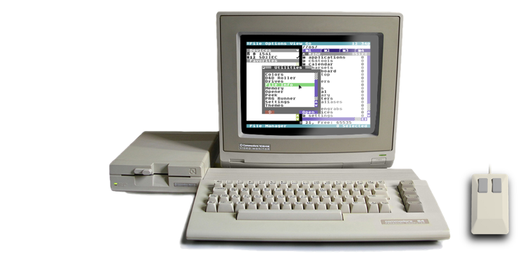
Sam's Journey is my go-to game for testing these controller mods.


Works like a charm. And looks really sharp on the desk.
Now, when I first got these four controllers, the first thing I did was test them out on a NES. Three of them worked flawlessly. But one of them had a bummed "left" button. I was playing Super Mario Bros. 1, and you could not walk Mario left! This contributed to my belief that these controllers were unimaginably cheap.
The problem, as it turns out, is that the cable had not been seated inside properly. It was partially under the silicone insert for D-Pad buttons, and was lifting it or moving it out of place. The PCB, and the IC, and even the buttons themselves were fine. The misfunctioning controller was the first one I did, and the conversion fixed the problem.
Taking it a Step Further: Select and Start
I remember, many years ago, probably in the early 2000s, but maybe even the late 1990s, a conversation I had on IRC with Vanessa Dannenberg. She suggested that a C64 controller could have additional functional buttons, without needing extra lines, without a shift register, and still maintain backwards compatiblity with existing games. This intrigued me. The conversation has stuck with me for nearly 20 years.
The idea is to wire impossible combinations of buttons to additional buttons. For example, you cannot ever push Up and Down at the same time. So if the computer ever had both of those lines pulled low together, it could assume the push of an additional button. Similarly, you cannot ever push Left and Right at the same time. That combination could be assigned to another button.
When I tweeted about this not long ago, someone pointed out that there are other impossible combinations:
Up+down+left, up+down+right, left+right+up, left+right+down, left+right+up+down are also not doable with a real joystick. All according bits set at the same time could lead into additional buttons aswell
— lubber (@lubber2009) October 2, 2018
That's true, but after thinking about it for a bit there is a problem. Let's say you do assign a button to Up+Down. Once you press that button, obviously you can't use that in combination with either Up or Down, however, you can use that new button in combination with Left and Right. In other words, once you assign a new button to one impossible combination, other formerly impossible combinations suddenly become possible.
The fact that one of these buttons cannot be combined with Up or Down, and the other cannot be combined with Left or Right, makes it a tough sell for using these buttons in an action or arcade situation. I mean, imagine you had a Commando-style game. The character can walk in any direction, imagine you wanted to assign 3 weapons to three different buttons: Fire, plus the two new buttons. It just wouldn't work out that well. The moment you tried to use one of those new buttons to shoot, your ability to simultaneously walk in any direction would be impaired.
There are situations, though, where I think it would be very useful. In Sam's Journey, for example, you have to press the Space Bar to pause the game and call up the in-game menu for quitting the level or saving your progress. Such a menu could easily be triggered with one of these new buttons. It wouldn't interfere with game play, because you generally use it when you're at a break in game play. But it also wouldn't require you to reach out and press the space bar.
Another example I've thought of. In Hessian (fantastic game, by the way,) you use the < and > keys to cycle back and forth through your weapons and other items. This could very easily be accomplished by holding one of the new buttons down, and then pushing Left or Right to move through the weapons. You generally don't select your weapon at the same time that you're running and shooting. Currently, you have to take your hand off the controller to use the keyboard anyway.
Furthermore, the NES controller happens to have 2 and only 2 extra buttons: Select and Start. They are not positioned to be used as action/arcade fire buttons, either. They are literally perfect for the usecase I'm describing.
If real life were Dungeons and Dragons, my ability score at electronics would be around 2. I've spent much more of my cognitive energy figuring out how to code. But I do like electronics, and I'm learning more all the time. For a button on a controller to register with the C64 as being pressed, it needs to sink current, aka, it needs to connect to ground. That's because the CIA port lines internally pull up when left floating. But you can force them low by connecting them to ground.1
In order for one new button (say, Select) to connect to ground two other buttons (say, Left and Right), the positive poles of Left and Right have to be connected together at the positive pole of the Select button. But they can't literally just be connected together with ordinary wire. If they were, Left and Right would be electrically connected, and could no longer be distinguished from one another.
The solution is to use diodes instead, which are one-way semi-conductors. The result is that current cannot flow between Left and Right, but can flow from Left to Select, and from Right to Select. In order to test this out I made a quick simulation with iCircuit. iCircuit is free for Mac and Windows, and costs $14 (Canadian) for iPhone or iPad. It's not a professional-grade tool, but it's inexpensive and easy to use. For hobbyists like me it's ideal. Here's what the simulation looks like:
Download this circuit simulation for iCircuit here.
How Does This Circuit Work?
The circuit is divided roughly in half, right across the middle. There are 6 lines that connect the bottom half to the top half. Those 6 wires are the 6 wires found in a typical Commodore or Atari joystick: Up, Down, Left, Right, Fire and Ground.
The top half simulates the CIA, the test software and its output to screen. The bottom half is the wiring of the buttons in the controller itself.
Let's start with the top half. The CIA's port lines pull up to +5 VDC when they're left hanging. And, they are left hanging whenever no buttons are being held down in the controller. This behavior is simulated with pull-up resistors. The line level is then connected to an inverter, and the inverters are connected to binary-to-decimal 7-segment display decoders. And then the decoder is connected to a 7-segment display to actually show the value. The inverters, converters and displays simulate what the test software does. Each of the controller lines is connected to the appropriate bit. Up is b0, Down is b1, Left is b2, Right is b3, and Fire is b4 (the zeroth bit of the high nybble). Neither controller port connects to bits 5, 6 or 7.
In the bottom half, the ground line from the controller cable connects to each of the 8 buttons. On the controller's PCB, there is one common ground that all the buttons are connected to, that connected to the ground line of the original NES cable.
Each of the regular buttons, Up, Down, Left, Right and Button B, is connected up directly to its own bit. Button A is connected to the switch. The switch joins up to Button B, or Up, alternatively. And that's where the original modification ends, with Select and Start not wired to anything.
Now, Select has one diode connecting it to Up, and another diode connecting it to Down. The direction of the diode points from Up to Select, and from Down to Select. That's because positive current has to flow from the CIA's Up line, through the diode, through the closed Select switch and into Ground. Similarly, positive current has to flow from the CIA's Down line, through the diode, through the same closed Select switch and into Ground.2
If, on the other hand, you release Select, and just press Up. Current can flow from the CIA's Up line, through the closed Up button and into Ground. Current from the CIA's Down line, though, cannot flow backwards through the one-way diode into the closed Up button and into Ground. The screenshot shows the Start Button depressed, and the Yellow lines show how current flows through the diodes connected from Left and Right, (bits 2 and 3, values 4 and 8) to combine together to produce the "impossible" combination of "C" on the digital display.
According to the simulation, it works!
Making it Real
I drilled additional holes through the positive-side pads for Select and Start. And simply ran the diodes between the appropriate holes, and soldered them on the other side and clipped away the excess wire.
Select going to Down, runs along the botton. And Start going to Left and Right can run through the middle without crossing over the diode between Select and Down. However, for Select to go to Up, it has to cross over the two diodes running to Start. In order to not have these cross over each other, I put that diode on the other side of the PCB. It doesn't get in the way of anything, it doesn't make any unwanted shorts, so doing that worked a charm.
Wiring up Select and Start couldn't be easier. It's just two extra holes drilled, and 4 diodes strung between the holes.


The only thing left to do is test it out. It's easy enough to test with existing games that the main controls are still working as expected, including the A Button switch. But, to test the behavior of Select and Start we need to write some code.
Note: I misspeak around time index 4:00, I say up is bit 1, I meant to say it's bit0.
Here's the source code for the test code.
Conclusion
Well, that's all there really is to it folks. Now all we need to do is get some games to actually make use of these new buttons. But, at least the controllers are backwards compatible with games that don't support the new buttons.
I am going to add a 4 controller driver to C64 OS, that produces digital controller events that can be distributed via the main event loop. Supporting input from 4 controllers in C64 OS applications will be very easy. I'm also thinking that I'll remap the "impossible" combinations to alternative bits in the 1-byte event. Such that every bit in the event has a one and only one meaning.
Like this:
| Bit | Value | Meaning |
|---|---|---|
| 0 | 1 | Up |
| 1 | 2 | Down |
| 2 | 4 | Left |
| 3 | 8 | Right |
| 4 | 16 | Fire |
| 5 | 32 | Select |
| 6 | 64 | Start |
| 7 | 128 | reserved |
Enjoy your Commodore 64! Over and out.
- For all the details on exactly how this works, read my post about How the C64 Keyboard Works. It's about the keyboard specifically, but the controller ports are connected to the CIA in almost the same way, except that ground is connected to permenant ground, rather than to the other CIA port. [↩]
- The notion of positive current "flowing" from a positive source to ground is the conventional conceptualization of electronics. It pre-dates the discovery that it is electrons which move, and so it is actually negative charge that "flows," and it flows in the opposite direction. But it doesn't really matter which way you choose to imagine it. [↩]
Do you like what you see?
You've just read one of my high-quality, long-form, weblog posts, for free! First, thank you for your interest, it makes producing this content feel worthwhile. I love to hear your input and feedback in the forums below. And I do my best to answer every question.
I'm creating C64 OS and documenting my progress along the way, to give something to you and contribute to the Commodore community. Please consider purchasing one of the items I am currently offering or making a small donation, to help me continue to bring you updates, in-depth technical discussions and programming reference. Your generous support is greatly appreciated.
Greg Naçu — C64OS.com