NEWS, EDITORIALS, REFERENCE
I2C Serial Bus in 6502
Let me give some context for why this project exists. Then I'll go into some detail on what I discovered, and we'll explore how the i2c bus and protocol works and dive deep into my 6502 implementation.
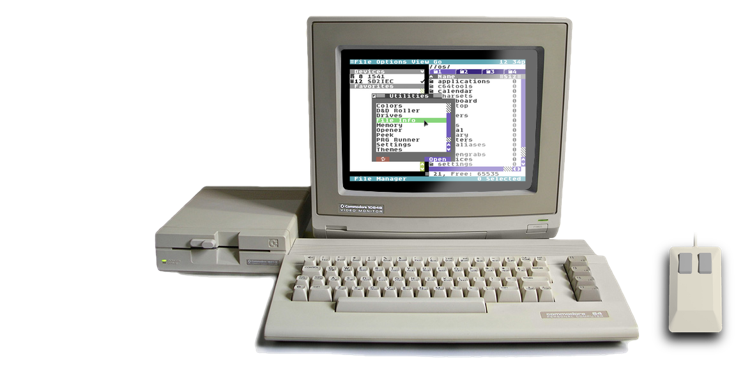
I'm working on an operating system, C64 OS, for the Commodore 64. An operating system can almost always benefit by knowing the current date and time. At the very least because it's useful for setting the clock that appears at the end of the menu bar.
The C64 didn't originally ship with a built-in realtime clock, nor did it include a standard port for an RTC, like the later Amiga did with its clock port. With the arrival of more advanced operating systems, such as GEOS, several options for accessing an RTC became available, but there was no one standard. Creative Micro Designs, CMD, always eager to make the C64/128 productive, embedded RTCs into most of their products. The CMD HD, the CMD FD, the CMD RamLink and the CMD SmartMouse, all included RTCs. For the storage devices, the RTC is accessed as a standard DOS command and the response is read from the device's error channel. In other words, the communications with these RTCs is piggybacked on the IEC serial bus, for which there is already an implementation built into the C64's KERNAL ROM.
The SmartMouse must have employed a different and custom communications method.
SD2IEC, for which I have written a full user manual, has support for an RTC in the firmware, that is nearly 100% compatible with the CMD storage devices, but most SD2IEC hardware implementations don't actually include one.
The IDE64 has an RTC, but I haven't yet explored how to talk to it. The 1541 Ultimate II+ and the Ultimate 64 have an RTC built in, and it is accessible using Ultimate DOS commands which are sent over its proprietary Ultimate Command Interface. This requires some effort to actually support, but it's not too hard. C64 OS already includes an RTC driver for the Ultimate Command Interface.
The 1541 UII+, the Ultimate 64 and IDE64 are, however, outside the budget of many potential C64 OS users. And the CMD devices are no longer commercially available. In all likelihood a typical C64 OS user will gain access via the minimum hardware requirements of an SD2IEC. They are likely, however, to end up with one that does not include an RTC. It would therefore be convenient if they could acquire an affordable, stand-alone, RTC module. Of course, such modules exist for the Arduino. The DS3231, costs less than $2. A very affordable, convenient addition that makes your C64 running C64 OS better.

Support for DS3231
I can't recall now how I stumbled upon this C64 projects page. With the heading T.V. Home it took me a while to realize that T.V. were the initials of Timo Voutilainen, the guy whose page it is. I likely found it while searching the web for C64 hardware products and projects for the Commodore 8-bit Buyer's Guide. Timo has a bunch of projects, but we can return to some of those at the end.
UPDATE: February 5, 2020
Apologies, I had named Timo Voutilainen "Tim", that was my honest mistake. His name is Timo.
Of interest to me, one of his projects is a small RTC module, a DS3231, connected to the User Port. I wanted to explore this as an RTC option for C64 OS, and at their low price, I ordered 3 of them from Ebay.
Unfortunately, Timo's project page for the DS3231 doesn't go into much detail on how this works. The page describes which pins of the User Port to connect to which pins of the DS3231. It explains that a small surface mount resistor should be removed, and gives a couple of other electrical notes and warnings. It also includes a download of some utilities and a driver for GEOS, with a brief description of how to use these.
I downloaded the package of utilities. I also ordered a couple of User Port reset switches from poly.play. These are just little female to male passthrough boards with a reset button. I got them because they provide a cheap and convenient place to solder wires for connecting the DS3231, but they leave the User Port open for another device to be connected. We'll return to this in a minute, too.
Long story short, it worked exactly as Timo described. I didn't try the GEOS driver, but there are programs you can load and run from the READY prompt, one to set the time and another that reads out the time and sets the TOD clock in one of the CIAs and sets the C64's BASIC time. And that all worked.
Very cool. But there were at least two things I wanted to accomplish:
- Be able to read the RTC from inside C64 OS
- Make the RTC compatible with User Port WiFi modems
Compatibility Concerns
Before worrying about how to get this into C64 OS, I wanted to figure out if it would be possible to use this RTC on the User Port at the same time as using a WiFi modem.
WiFi modems have become quite popular, and I want to support them as first class citizens for networking in C64 OS. It makes no sense—no one would want—to lose compatibility with their WiFi modem just to have the time set automatically. That's much too big a sacrifice.
I wrote a post about Chess and Networking a few months ago, the networking part of that post is particularly relevant here. The C64's KERNAL ROM implements a TTL-voltage level version of RS-232. Many User Port devices, like WiFi modems as well as regular dialup modems, communicate with the C64 by simply using RS-232 as the protocol.
The User Port is a 24 pin edge connector. 12 on top, 12 on bottom. All four corners are for GND. On the bottom row, just inside from the two GNDs, you have Port A bit 2 on one end, and the CIA 2's /FLAG line. Both the Port A bit 2 and the /FLAG line are essential for implementing R2-232, by the way. That leaves 8 pins centered on the bottom. These 8 pins are the full Port B.
RS-232 only uses a handful of these lines. It doesn't use bits 2 and 3 of Port B, for example. It does, however, use bits 0 and 1, and these are just the bits that Timo Voutilainen's project and software are using for the DS3231 RTC. The question then is, however the DS3231 works, would it be possible to make it work on bits 2 and 3, such that it would not interfere with the presence of a WiFi modem, or any other RS-232 device for that matter.
I2C Serial Bus
I didn't know how it worked and I didn't have the source code, so tried to disassemble it, to see if I could reverse engineer it. This turned out to be way harder than I was expecting. I couldn't make heads or tails of what the code was doing. So I sent Timo an email, explained what I was trying to do and asked him if I could get a copy of the source code.
I should have thought of that first, because he was interested in my ideas and was eager to help. He sent me his source code, but it was written in C. That's okay, I can program in C, and it would at least let me see how it's implemented, and then I could try to port it to 6502 assembly.
What I discovered is that the DS3231, like many hundreds, maybe thousands of devices out there communicates over a serial bus called I2C. I'd never heard of I2C before, but now I had something I could go read about, which I will summarize for you.
I2C bus stands for Inter-Integrated Circuit bus. It was developed in 1982 by Philips. Anything developed in 1982 is probably going to be reasonably straightforward to implement. It is a serial bus that requires just two lines, a clock line and a data line. The bus supports multiple masters (communications controllers), and multiple slaves (devices on the bus each with a unique address.)
The C64 is an example of a master, but in theory you could have more than one master, other computers or microcontrollers connected to the same bus. For our purposes we don't really need to worry about any details of multi-master support. It is enough to say that whenever a master wants to start using the bus it begins with a start signal. It's possible for two masters to have a start signal collision, in which case there is a way to resolve who wins. After a master successfully issues the start signal, it owns the bus until it eventually issues a stop signal.
Once a master is in control of the bus, it is that master who always generates the clock signals. Each clock cycle indicates that a new bit is available on the data line. If you aren't familiar with how this works, a simple example can been seen in how a computer (or a Nintendo NES), the master, reads data from a Nintendo NES Controller, the slave. I go into a fair amount of detail about how a clock line can be used to read in one bit at a time, in my first post, NES to C64 Controller Mod.
Immediately following the start signal, the master sends a write message with a device address, and waits for the device to send an acknowledge signal. If no acknowledge is received within a short time, the device is assumed to not be on the bus. Otherwise, the master writes a register number to the bus, which is interpreted by the device that was just addressed. Now to read from that device's register, the master sends another start signal. Immediately following the start signal it sends a read message with the device's address again. All subsequent reads from the bus will be coming from that register of the addressed device. After reading each byte the master sends an acknowledge, and the slave device prepares the next byte. When the master has read the last byte it wants, it sends a no-acknowledge, so the slave doesn't prepare the next byte. Then, lastly, the master sends a stop signal. This releases the bus. If there were another master on the bus, that other master could then send a start signal of its own.
That is the protocol in a nutshell.
What's so interesting is that the bus only needs two User Port lines, one for clock and one for data, and can easily have multiple I2C devices connected at the same time.
I2C6502
So where does this leave us? The DS3231 is just a standard I2C device. Therefore, what we need to do is have a working implementation of the I2C bus, by manipulating two lines of CIA 2, just as the KERNAL ROM implements RS-232 by manipulating CIA 2 lines. The main difference is that RS-232 was designed in 1960, 22 years earlier than I2C. Even though I2C is now 38 years old, compared to 60-year-old RS-232, I2C is simultaneously simpler and much more flexible. But they are both still useful for quite different purposes. And there are certainly some things that RS-232 does that I2C does not or could not.1
I picked over Timo's C implementation until I understood it, and then sat down and ported it to 6502 assembly. This took a surprisingly short time, only a couple of hours. And after Timo helped me work through a couple of bugs, I got it working. Once you actually have the I2C protocol up and running, using it to read and write data from and to registers in the DS3231 is an absolute breeze, so we'll come back to that after discussing the I2C implementation itself.
Let's dive into the details of how it works.
Layers of Abstraction: Hardware
At the lowest level, we have the CIA 2 chip and in particular its general I/O Port B. There is a C64 address for reading/writing data to this port, and an address for setting the data direction of the bits on this port. And within the port, we have the two specific bits we want to use, one for clock and one for data.
The bits will be named SDA for data and SCL for clock. Throughout the implementation the direction of these two lines needs to be toggled between input and output. So we have four routines to do just that: sda_out, sda_in, scl_out and scl_in. One shortcut, both_out, will call sda_out and fall through to scl_out, which saves a tiny bit of code down the road.
These routines first read the data direction register, then flip on or off only their one bit, being careful to leave the others unmodified, and write the result back to the data direction register. In theory this will not break RS-232.
On the next level up, all facets of the communications are done by reading and writing individual bits from/to the SDA and SCL lines. For example, the start and stop signals the acknowledge and not-acknowledge signals, are all done with prescribed ordered manipulations of these two lines. Therefore, we need four more routines: sda_read, scl_read, sda_write, scl_write. I can't recall where I learned this, but in 6502 the easiest way to read and write individual bits is via the carry.
The reason is because, when you write a whole byte down a serial line, you need to send one bit at a time. The easiest way to do this is to roll or shift the byte which causes the next bit to end up in the carry. Or, if you're reading a byte from a serial line, you need to shift the incoming bits into a byte, which is again easiest by having the bit read into the carry and then rolling all the existing bits up and rolling the carry into the bit 0. Additionally, it's very easy to branch on the state of the carry with BCC or BCS. This is easier and faster than, say, hold the bit in the accumulator, because before you use BEQ or BNE you have to compare the accumulator to 0 (CMP #0).
When reading, we read the data register, mask away all the other bits, and depending on whether the result is zero or not zero, we clear or set the carry respectively and return. When writing a bit, we always read the data register first to get its current state. Then, if the carry is clear we clear just that one specific bit, or if the carry is set we set that one specific bit, and write the result back to the data register. This, also in theory, should not have any interfering consequences for RS-232.
Believe it or not, these 8 simple low-level routines completely abstract the hardware layer. At every level of abstraction above this we are simply setting the direction of SDA and SCL, and reading and writing bits from and to SDA and SCL, getting and setting via the carry. What SDA and SCL actually are is totally opaque to the rest of the protocol. I really like that.
Layers of Abstraction: Bus Signaling
There are 6 routines used to manage bus signaling. These are not about reading and writing data but all of the support signals that wrap the data calls.
- i2c_init
- i2c_reset
- i2c_start
- i2c_stop
- i2c_ack
- i2c_nack
i2c_init initializes the I2C bus. This call is embedded into the RTC set and get utilities. But I'm not sure how often this needs to be done. It could be that you use one of those utilities just after starting up the computer. In the context of an OS, though, with an I2C bus protocol, I assume it only needs to be done once. i2c_reset is used to reset the bus if, somehow, it gets stuck. Like, maybe if a master gets control of it, and then the master crashes and never releases it. I'm not sure. The RTC utilities that Timo wrote don't ever use this. In my own use I've temporarily commented this out to save space.
i2c_start is used by a master to assert temporary ownership of the bus. i2c_stop is used by the master to release control of the bus. These two signals wrap a packet of communication. The protocol expects that an addressing command, defined at a higher level, will follow a start signal. The stop signal also informs any slave that is currently being communicated with that the communication has ended. If the master was reading from it, the master will read no more. If the master was writing to it, the master will write no more.
i2c_ack and i2c_nack are how the master sends an acknowledge or a not-acknowledge signal. These are sent only when the master is reading data from the slave. After reading a full byte, if it wants to read more, it sends an acknowledge. After reading the last byte it sends a not-acknowledge just before sending the stop signal.
Receiving an acknowledge or a not-acknowledge from a slave device is only done while writing data, and is inline with the code at the higher level for sending data.
This feels like a lot of picky code. I don't really know exactly how this stuff works. I just know that it's the prescription of the protocol for how to send these types of signals. The other master and slave devices know how to interpret these signals, but I simply copied them from Timo's C implementation and they work.
Two supporting elements are introduced. The delay routine. The I2C bus runs at a limited speed. If the 6510 and the CIAs were clocked at hundreds of megahertz or more, simply flipping the SDA and SCL lines up and down as quickly as possible would not give the slave devices enough time to read or write data between the clock signals. My guess is that on a PC the implementation of an I2C bus is done with a custom microcontroller that runs much slower than the CPU, and much closer to the I2C's bus speed. For the C64, which is only running at 1Mhz, we only need to delay by a handful of clock cycles before reading or writing the next bit. The delay routine is nothing but a set of NOPs that waste a few cycles while the slave gets a bit of time to deal with the data line.
Response codes are introduced here as well. There are two error codes that, under circumstances that I'm not quite sure about, will only ever get produced during the bus initialization. Other routines that could fail, such as i2c_stop and others we'll see soon, will return either ret_ok or ret_nok to indicate success or failure.
Layers of Abstraction: Byte-Sized Communication
Now that we have the tools to communicate in individual bits, and we have some higher level signaling, we're ready to read and write full bytes across the bus.
I2C only operates on one byte at a time. This makes things very convenient for our 8-bit computers. And so we introduce two byte-level routines: i2c_readb and i2c_writeb.
i2c_read fetches a byte from the bus. It initializes a data byte to 0. And loops 8 times with a delay per loop. The process basically consists of raise the clock line, delay, read the data line, roll the bit just read onto the data byte, lower the clock line, delay, and repeat 8 times.
The final data byte is returned in the accumulator. The Y register is not disrupted by this routine.
i2c_write is slightly more complicated. The first byte after a start signal is usually an address write. In I2C every slave on the bus must have an address. But these addresses are only 7-bit. After the start signal, the 7 bit address is sent, followed by one more bit used for data direction. 0 if the master wants to write to the slave, or 1 if the master wants to read from the slave.
There are two ways to write a byte then. To write an address, you put the 7-bit address in the accumulator, and you put the data direction in the X register. The X register also functions as a flag for whether you are writing an address or just writing a regular byte.
The possible values for X are: purebyte = $ff (aka -1, the high bit is set), writebit = $00 or readbit = $01. X is checked to see if it's negative. If it's negative then the value passed in the accumulator is written to the bus unmodified. If X is not negative, the low bit of X is used as the data direction bit. It is right shifted into the carry, and then rolled left onto the data byte. This has the effect of shifting the 7-bit address up one bit, and putting the data direction bit into bit 0.
From there, all writing is the same. Roll one bit off the data byte into the carry, and set on the data line, delay, raise the clock line to indicate the presence of a new bit, delay, lower the clock line, repeat 8 times to write out the whole byte.
After writing a byte, it is necessary to get an acknowledge signal from the slave we've been writing to. This is very simple. It involves setting the SDA for input, and then waiting for the slave to pull the line low. To do this we just read the SDA line. If it's low we can branch out of this loop. If it's still high, we delay, decrement a timeout counter, and if the timeout is still valid, loop to check again. If the timeout counts all the way down to zero and the line is never pulled low, the response ret_nok is returned in the accumulator. It's an error, because we sent a byte but the slave never acknowledged its receipt.
The timeout is adjustable. Timo set it to 50 tries. That seems to work, but it would probably still work even if set lower. If the slave acknowledges within the timeout period, there is some minor ajustment to the data direction of SCL and SDA, and then ret_ok is returned in the accumulator.
Layers of Abstraction: Register-Level Communication
Lastly, we come to the highest level of abstraction, the ability to read and write device registers. The whole I2C6502 library begins with a jump table. The jump table exposes to outside code the library routines that can be called. It exposes i2c_init and i2c_reset. This allows other parts of the operating system, or your standalone program, to init and reset the bus.
The only three additional routines exposed are for reading and writing device registers. Your outside code has no access to any of the lower layers. No byte reading and writing, no bit reading and writing, no special signaling (besides init and reset), and definitely no insight into which bits on the port are being used and in what direction they are being set.
There are three routines: i2c_prep_rw, i2c_readreg and i2c_writereg.
i2c_prep_rw is a preparatory routine that configures a pointer to a buffer, into which to read or out of which to write data. And a data length to read or write.
i2c_readreg reads data from a device register. The device's address is passed in the accumulator, the register to read from is passed in the Y register. Typically the carry should be cleared. But, it can be set for some special devices to skip writing the device address first.
There is nothing else to do. The device will be addressed, a read from the specified register will be requested. And then the length of data specified in i2c_prep_rw will be read from the register into the buffer. If all went off without a hook, it returns with ret_ok. If any problem occurred in the middle, it returns with ret_nok.
i2c_writereg is even simpler than i2c_readreg. It takes the device address in the accumulator and the device register to write to in the Y register. It then writes out the length of data specified in i2c_prep_rw, from the buffer. If everything works, it returns with ret_ok. If there was any problem, it returns with ret_nok.
And that is all there is to it.
I should note that the read/write buffer can only be 255 bytes long.
Also, reading and writing from the buffer requires putting a pointer into zero page. The zero page addresses used are $FB and $FC. These, in C64 OS, are reserved for application use, and are never touched by the interrupt handler. I2C6502 backups and restores these addresses before and after using them. So, it shouldn't ever conflict with any application that is using those addresses.
The full source to I2C6502 can be found at: https://github.com/gnacu/i2c6502
I have since done some optimizations on the code in the respository, and I spotted a few more improvements I can make just while discussing it for this blog post. But, even still, this implementation is only around 600 bytes! That's pretty small.
It's amazing to me that anything can be accomplished in just 600 bytes. But, that's part of what is so fun about the C64. We have the IEC serial bus, we have RS-232 and now with a library like this we have the I2C serial bus protocol. Just see the end of this post for examples of some of the very cool stuff that Timo has done with his C implementation of this bus.
Reading the DS3231 RTC over I2C
Now that we have a full I2C bus implemented, and simple routines to call to read and write the registers of devices by their address, the hardest part about writing an RTC utility is the UI2 to present the results.
You can find the source code to ds3231rtc.asm in the I2C6502 repository. And I don't want to go into detail about the uninteresting bits of how it works. Instead, I'll summarize just the part needed to read the time from the DS3231 RTC module.
That's it!
The I2C6502 library has to be assembled to somewhere. By default I've got it assembling to $2000. In this code then, we need to specify the location where the I2C6502 library can be found, i2cbase. Then we have constants for its 5 jump table entries. This stuff would probably be put in a header that could be included.
ds3231addr is defined as the device's address, $68.
dssecreg is set to $00, and this is technically its "seconds" register. However, the registers are sequentially numbered in the device, one byte each: seconds, minutes, hours, day of week, date, month and 2-digit year. If we read from the seconds register, but we read 3 bytes, we'll read in just the seconds, minutes and hours. If we read 7 bytes, we'll get all of the fields. And if we wanted to read in just date, month and year, we could start reading from the date register ($04) and read 3 bytes.
We need a buffer into which to read the data. This all comes at the bottom. And a constant for the total data size of 7.
After initializing the bus, we grab a pointer to the buffer, and the length to read, and we call i2cbase+prep_rw_. To configure the buffer and data length.
Next we load the device address into .A and the seconds register into .Y, clear the carry to be sure to send the address byte. Then call i2cbase+readreg_. And that's it! The data is thereafter available in the buffer.
So reading data from the device with the I2C6502 library is very easy. Writing data to the device is similarly easy. Simply put the data into the buffer that you want to write out. Then, instead of calling i2cbase+readreg_, call i2cbase+writereg_.
It couldn't be any easier!
Testing for RS-232 Compatibility
That was a lot of theory about not messing with the bits that RS-232 uses, but can we really use both protocols on the User Port at the same time?
Using the little User Port reset button I got from poly.play, I soldered terminal pins onto the socket connector. On the top, one for GND and one for +5VDC. And then on the bottom I put one terminal pin on each of the bits of Port B. This way I can easily move the SCL and SDA lines of the RTC around to different pins to test them out.
I opened up one of the WiFi modems I have, and tested and confirmed that bits 2 and 3 (Lines E and F on the User Port) are in fact not wired up to anything at all.
The reset switch board is plugged into the User Port and the WiFi modem is plugged into its passthrough. And, it works! Both power up, and if I run my I2C6502 code, I can read or set the time on the RTC. The presence of the modem doesn't interfere. Next, I boot into Novaterm and lo' and behold, it can access the modem no problem. After using the modem for a while, I quit Novaterm and try out the RTC utility again, and it reads from the I2C bus no problem. It certainly seems to work. That's great news.


Other I2C Projects
Once you have the I2C bus written, reading and writing the registers of a whole variety of devices becomes absolutely trivial. Timo Voutilainen has done just this, and written a whole series of fun and useful applications that are ultimately just nice front ends to simple communications with a variety of different I2C devices.
WireMon64https://sites.google.com/site/dividedbit/home/c64-projects/wiremon
This is a very cool program, that is the closest thing to home automation that we've got with our C64. It can control lights in his house, and report on temperature and humidity, and do motion detection in the hallway or on the deck. And if you add an RTC to this, you could use the C64 for scheduling changes to be written to these devices.
I'm not actually sure how far Timo has taken this, but, the imagination starts to light up and you realize that the C64 could actually be used to monitor and automate quite a lot of things. Very cool stuff!


It would be so cool to write this as a C64 OS application. It could be given a very intuitive UI by building it on top of the C64 OS object oriented toolkit.
FM Radio App for GEOShttps://sites.google.com/site/dividedbit/home/c64-projects/fm-radio-app-for-geos
Well, now I'm just jealous! This thing looks beautiful. And, it could be very useful as a C64 OS utility, you could pop open the utility, turn on and configure the radio. Close the utility and the radio continues to play. Making it a utility would be ideal, so that you could pop it up over top of whatever app you're currently in to change the station or turn it off.
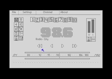

And he has other projects, like a GPS viewer and an MP3 Player! You really should check out the page.
It's really cool for the C64 to be open a new range of devices out there. The arduino community and the cool stuff they're doing bleeds into the retro computer world in many fun and interesting ways. But this is not one that I was paying any attention to.
Getting access to an inexpensive RTC is handy for C64 OS. But, the real fun is in all the other cool little I2C modules that we could write applications for. Hopefully someone will take my 6502 implementation and make use of it!
- For example, a slave cannot initiate a transfer to a master. Whereas an RS-232 connection is truly 2 way. A modem can send a data word to the computer at any time. [↩]
- I should point out that the object-oriented toolkit in C64 OS, with its mouse and menus are all about making an advanced UI fast and easy to write. [↩]
Do you like what you see?
You've just read one of my high-quality, long-form, weblog posts, for free! First, thank you for your interest, it makes producing this content feel worthwhile. I love to hear your input and feedback in the forums below. And I do my best to answer every question.
I'm creating C64 OS and documenting my progress along the way, to give something to you and contribute to the Commodore community. Please consider purchasing one of the items I am currently offering or making a small donation, to help me continue to bring you updates, in-depth technical discussions and programming reference. Your generous support is greatly appreciated.
Greg Naçu — C64OS.com