Content
- Welcome Page
- Order C64 OS
- C64 OS User's Guide
- C64 OS System Updates
- Weblog Full Archive
- Commodore 8-Bit Buyer's Guide
Before I actually got anywhere near to working on the front panel, I'd already solved the problem of how to mount and pass the I/O ports through the relatively thick (3/4") wood chassis. I'd solved that problem at the Rear Panel. The solution was, rather than trying to cut precise holes through thick and uncooperative wood, I cut a large squared-off opening in the wood. The ports are then mounted on a removable mount board, which itself is bolted to the bottom of the chassis.
A thin piece of sheet aluminum is then cut slightly larger than the opening in the wood, so its edges overlap and just cover over that opening. From there, it is much easier to dremel more precise holes through thin aluminum than it is through wood. Additionally, the cables only need to pass through a very thin metal layer before reaching the jack.
As we'll see, this technique works out as well for the Front I/O Panel as it did for the Rear I/O Panel. But first, I will describe the speakers and how they are mounted into the front panel of the wood chassis.
As I began discussing in Front I/O: Volume Control, the three main components of a sound system consists of: a source (the C64), a receiver or amplifier (the DROK TDA7297 DC Micro Digital Amplifier), and a set of speakers. The previous section describes the digital amplifier and its installation. Now it's time to talk about the speakers.
Ebay to the rescue again. It is a veritable cornucopia of speakers of every size, shape and description, for prices ranging from a few dollars per speaker to a few hundred dollars per speaker. The front panel of C64 Luggable is wider than it is tall, so height is the limitation on speaker size.
The front panel, according to the description in the section Chassis Assembly, is 6 1/8"W x 14 1/2"H. But, the speakers can't be that full size for a couple of reasons. The front panel is to be screwed onto the two sides. Each side is 3/4" thick. The speakers obviously cannot encroach into this space. So from the front they have to sit in at least 3/4" from either side. For aesthetic reasons, but also for reasons of structural integrity and the speakers cannot sit flush with the top of the front panel either.
I drew lines on the front to mark the left and right 3/4" margins. In order to make them look balanced then, I drew a similar line width-wise, 3/4" inset from the top. Whatever diameter of speaker I choose has to have its top and left edges just inside these margins. Additionally, there is the row of Front I/O ports, power switch and volume knob, that have to fit below and between the speakers. The volume knob sits up the highest, plus you need a bit of extra space around that for the metal cover plate.
Just by measuring, I found that there was just enough space for speakers with 3.5" of diameter, including the mounting frame. You need to be aware, when shopping for speakers, that they are usually measured as the diameter of the cone, the part that moves to produce sound. The cone, though, is attached to a metal frame used to mount the speaker in a cabinet, or a car door, or homemade Commodore 64 chassis. The frame sizes do vary, but they are by and large fairly standardized. Therefore, a 3" speaker, can be expected to have a 3.5" frame diameter. I searched eBay and found quite a few that would fit the bill.

I'm anything but an audiophile, but when it comes to speakers, no matter how forgiving you are as a listener, a few things still matter. You have to match the characteristics and capabilities of your amplifier with the characteristics of the speakers. The most important match has to be the impedance level. For a layman's description that goes into much more detail than is reasonable for this site, you could read this: Meditations on Speaker Impedance.
In short, speakers have an impedance that, like resistence, is measured in Ohms. Typical ratings are 4 Ohms, 8 Ohms or 16 Ohms. Your amplifier also has an Ohm rating that it is designed and suitable to drive. Speakers with lower impedance need to suck more power out of the amp to produce the same volume. If the amp cannot handle the draw, it can overheat. This can damage the amplifier, and who knows, it could catch fire or other bad things. My choice of amplifier was quite limited by the space constraints. However, the DROK amplifier specifically stated that it was suitable for driving either 4 Ohm or 8 Ohm speakers.
The next metric is power, which is measured in watts. An amplifier specifies the wattage it is capable of delivering. The speakers are rated for a number of watts they can handle of input. If your amplifer is overpowered, outputting more watts than the speakers can handle, the sound quality at high volume will suffer and sound distorted, and the speakers are probably being damaged. If on the other hand the amplifer cannot output anywhere near the power that the speakers can handle, it just means that you will not be able to drive the speakers to the volume level that they can technically handle. Ideally, you want these to be fairly closely matched, erring on the side of the speakers being higher watt than the amplifier. You don't want to damage the speakers when you turn the volume up, but you don't want to turn up the volume and find to your disappointment that your expensive high quality speakers are not particularly loud.
For audiophiles, I'm sure there are many other characteristics about both speakers and amplifiers that affect the sound quality. But to be honest, I'm just not that picky.
The first ones I decided to order were a pair of 3" (3.5" mounting frame), 20 watt, 4 Ohm speakers. Now, these aren't exactly the cats meow, but get the price: $19.99 USD. They were only 10 dollars each, free shipping, from Hong Kong. For the low price, I was willing to try them out. I figured if they were truly crappy, sounded crappy, or whatever, I could always replace them later with a better pair that had the same 3.5" diameter.
I waited on these speakers for months to arrive. And they never arrived. It was an excrutiating wait, because all I wanted to do was get my hands on these puppies so I could move forward with the project. Eventually I was given a refund and a weak apology. I found another pair, similar, but higher quality. 25W and 8 Ohms, shipping from California, for just $28 USD, plus shipping. They arrived just 7 days after I placed my order. One of these days I'll learn my lesson and start prioritizing orders from within North America.


The DROK amplifier was rated for either 4 Ohm or 8 Ohm. And ranging from 15W per channel to a peak of 25W per channel. (Two channels, left and right, C64 Luggable has one speaker per channel.) With the amplifier outputting that wattage, I would expect the whole to be louder with 8 Ohm speakers rather than 4 Ohm.
As soon as I got the speakers, before I even started trying to mount them into the chassis, I hooked them up to the amplifier with my homemade cables, and powered up the amplifer with the AT Power supply. And connected my iPhone to the input. I was testing this in my basement workshop, which is not a huge room, but it's realistic of where one might find oneself playing C64 games at a party with some friends. As I turn the volume up, somewhere just past half-volume it becomes louder than I am comfortable talking over. Turning it up to 3/4 volume it becomes really loud, way louder than I would ever reasonably set it to.
For my purposes, that's pretty great! And altogether very inexpensive.


The general idea with mounting a speaker is that you have a circular hole through the wood, through which the majority of the speaker passes. But then you have a larger, partially inset ring around the hole, through which the outer metal frame does not pass. The outer metal frame is then screwed into the inside of that inset ring, such that the front of the speaker sits perfectly flush with the surface of the front panel.
Now, there are tools, routing tools, that are specifically designed to produce these holes. They are fast and easy to use, and they produce nearly perfect holes the very first time. If you are in the business of making speaker cabinets, you'd be absolutely crazy to not have one of these special routers. The problem is that they are rather expensive, and they're not the sort of tool that I need to use frequently enough to justify the expense. I needed a cheaper way to get more or less the same result, even if I had to put in a lot more effort.
What I bought instead were two hole saws. These are designed to be connected to your electric drill, and cost only about $15 each. I bought a 3.5" saw, and a 3" saw, plus the mounting bit for an additional $8 or so. The mount bit has an actual drill bit that comes through the middle, and the hole saw snaps onto it surrounding the bit. The hole saw is basically a thin circular saw blade. The trick is how to use the combination of the two saw blade diameters to get the result I'm after.


The 3.5" circles were drawn in pencil on the front panel, top and sides flush with the 3/4" margin lines. Then I put a crosshair through those circles to find the middle. The first thing I did was drill pilot holes about half way through the panel in the centers of those crosshairs. Next, using the 3.5" hole saw, I positioned the bit into the existing pilot hole so that it would guide the hole saw to keep it pretty close to that outer circle.
The trick is to not pass all the way through with the 3.5" saw. Only saw down a depth equal to the thickness of the speaker's mounting frame. For me, that was about a 1/4". Here's what that ends up looking like:


The next step is to switch over to the 3" hole saw. Put the bit back into existing pilot hole. This has the benefit of centering the smaller saw in the middle of the ring you just made. This center 3" hole can then be sawn straight through.
Then do the same process on the other side for the other speaker. 3.5" saw first, 1/4" deep ring. Then 3" hole saw, all the way through. You end up with it looking like this:


It actually looks pretty good! You immediately get a pretty clear vision of how this thing is going to look when it gets the speakers in there.
Here's what it looks like when you just stick the front panel in there, to see its positioning and sizing in context.


The problem with the hole saws, as you may have noticed, is that between the 3.5" ring, and the inner 3" hole, a ring of wood flush with the surface has been left behind. This is clearly not supposed to be there. A router would remove this entirely in the process of taking out the 3.5" track.
For me, and my cheap saw holes, I had to use a more laborious process. The wood, hobbyboard, is pine. It's quite soft. And that raised ring is quite thin. I used a pair of pliers and worked my way around the whole ring, snapping off a small piece at a time. Starting at the top, pinch a section of the ring, and simply bend inwards towards the hole. The pieces come off with little effort.
The only downside is that it doesn't leave behind as smooth or consistent a surface as you would hope for. From an aesthetic standpoint it doesn't matter. It's all going to be below the speaker's frame, and completely hidden. But you need the speaker to be able to sit stably, flat and flush. The dremel is seriously my favourite tool. I just went over the inside of the track with a basic sanding bit until it smoothed out the bumps.
Here's a before and after of the left speaker hole.


After you mount a speaker into a cabinet, or a car door, or wherever, you usually add a speaker grill. This is for aesthetic, decorative purposes, but it also protects the speaker cone from accidental damage.
I said earlier that speaker sizes are more or less standard. I'm not sure if there is an official standard, but there are certainly many defacto standard sizes, and shapes. The ones I chose are circular, which perhaps the most common shape. I just needed to find grills that are 3.5". There are loads of these on eBay in every style, color and material, across a wide price range. I opted for a pair that are plastic, but look like shiny red chrome. They came with a removable black perforated metal grill. For the whopping price of, ready for it? $2.89 USD for the pair.
Both the speakers and the grills usually include some diagrams with more precise measurements, including the distance between the centers of the screw holes. You can check these out to confirm before you buy that they're an exact match. The reason it matters is because screws have to pass through the outer decorative grill ring, and then through the frame of the speakers. If those aren't a match, there is no other way to properly mount the grills.


That's what they look like when just placed there. As you can see, any imperfections in how you produce those speaker holes, you'll never notice.
Next step is to insert the speakers, and decide how you want the screw holes to be oriented. There are 4 screws. So they can either be oriented like a plus, or like an X (or, heaven for bid, just shoved in at random.) I opted for an X. Personal taste.
But I ran into a problem. The inset 3.5" ring was pretty tight. And I had to really push around the edges of the speaker frame to get it to fit in. On it's own this doesn't really bother me, I think I'd prefer them to be a snug fit than too loose. The problem is that after setting the grill down onto the speaker, it became obvious that the speaker was not sitting deep enough. The speakers look flush to the eye, but you need the grill ring to sit absolutely flush against the wood panel.


Although tempting, you really don't want to force things by just tightening the screws down. Wood can be quite unyielding, and the grill rings are just plastic. I didn't want to break them. Instead, it required quite a few passes with the dremel sander to gradually eat away just enough that the speakers continued to feel snug, but would sit deep enough for the grill to end up perfectly flush with the wood surface.


Once they're sitting flush, you can screw the grills down and everything holds together nicely.
I stuck the panel back into the front of the chassis just to get another look at how it looks with the speakers actually mounted in there. I think it looks pretty sharp. It'll look a lot nicer when the chassis gets painted, I think that red will really pop.


That's basically all there is to the speaker mounting. With one tiny exception. Though the speakers are round, they do have an orientation. Each speaker has two terminals, a wide positive and a narrow negative terminal. The speakers should be rotated such that the terminals are oriented towards the middle of the chassis. It doesn't matter too much, but orienting them to the middle will make it easier to access them and hook them up to the amplifier.
Once the speakers can be mounted, they'll need to be removed and set aside so they won't get damaged or be in the way while we work on making the whole for the Front I/O Board.
The Front I/O board is positioned inside the front chassis, in such a way that the four joystick controller ports are centered. The space between port 2 and port 3, therefore, is at the very center of the chassis. We want the cutout hole, and the metal plate that covers that hole to also be centered. The I/O board itself, strangely, end up not quite centered. I'm not sure how I managed to mismeasure that. But, it's not that big a deal, as you won't see it.
The easiest way to make the measurements for where the cutout to be is to eyeball it. By laying the front panel down in front of the chassis, with the I/O board already mounted inside, it's very easy to see and mark where the center should be, and where the outside edges have to be to allow the mount board to pass through.
The only thing to be careful of, is that the left and right edges of the cutout be the same distance from center.


Next question is, how high the cutout needs to be. Ideally, remember, the goal of the I/O mount boards is that despite the front and rear chassis panels being permenantly screwed down, these can still be removed. So I can get access to those components to repair or replace them, or even just to create alternative swappable mount boards with different port configurations. And trust me, when I say the front and back panels of the chassis will be permenantly attached, I really mean it. One screwed down, the cracks will be filled with wood filler, the whole thing sanded, primed and painted. There will be no way to remove the front panel once it's attached.
In order to remove the mount board, the cutout needs to be large enough that it surrounds all of the internal components. Width-wise, this is not a problem. Height-wise, this involves measuring what is the tallest component, and making the cutout just a hair taller than that. The tallest component, by far, is the amplifier. It's main amplifier IC is screwed to a rather large aluminum heatsink. That's necessary because the power it conducts generates a lot of heat.
And that's the first problem. Here's how it fits, internally. The speakers are "cone" shaped. That means the mounting frame is 3.5" diameter, but the widest part of the cone is just 3", and then that narrows somewhat until you reach the magnetic part at the back, which is 2.76" across. The whole speaker is also not terribly deep, the back of the magnetic part sits just 1.69" in from the front surface of the front panel. And the panel is 0.75" thick, so the speaker only sits 0.94", less than 1 inch, past the inside back surface of the front panel.
And it's a damn good thing that it's that shallow, because the heat sink of the amplifier actually extends up and behind the right speaker. So it fits, but there is no way the Front I/O board is going to be able to just slide out. The components actually overlap with the mounted speakers.
I thought about it for a bit, and this isn't necessarily as big a problem as it might seem. You could left up the front of the I/O board as you pull it out, and slide it out in kind of an arcing curve, so the heat sink slides down and below the speaker. That might work. Another possible solution I thought of would be to replace the heatsink with one that is the same size, or maybe even bigger, but that is wider and squatter. That's not impossible but I'd have to source one. I left it as a future consideration.
But there is another problem. The volume knob is also tall, and it's right near the front, with a round potentiometer that cannot be moved. In fact, if it were able to pass through the I/O cutout, the top of cutout would have to be higher than the bottom edge of the speakers. There is just no way it's going to fit. Well, it'll fit, but there is no way there will be enough room to be able to simply slide the I/O board in and out like I wanted. I made the cutout as tall as I reasonably could, and I'll show you in a moment what I had to do to fit that pot.


Only thing next to do is to carefully remove the cutout. You've got to be pretty careful about this, because it's coming pretty close to those speaker holes.
Doing the vertical cuts, from the bottom edge, is pretty easy, I actually did those with a sharp handsaw. However, doing that horizontal cut is surprisingly difficult. Of course, if you have the right tools, nothing is difficult. There are plenty of saws, drop saws, that are designed to cut into the surface of wood, without having an edge to start from. Alas, I don't have any of those tools. But I do have my handy dremel, which is ideal for making drop cuts.
The only issue with the dremel is that the blades were not big enough to get all the way through.

I clamped it to the workbench, and went as deep as I could go along one side with the dremel. Then I turned it over and went over the same path again from the other side. Unfortunately, even going from both sides was not enough get all the way through.
I ended up trying to crack it, by slowly working it back and forth, trying to fatigue the thin strip in the very middle that I wasn't able to get to with the dremel. This turned out to be a colossally bad idea. The wood is very soft, and before I knew what was going to happen, the rocking back and forth tore a chunk out of the then bridge between the I/O opening and the speaker holes, on both sides. Argh.
Once the piece was removed however, it was easy using sandpaper and the dremel's sanding bits to smooth out the inside of the opening. Fortunately, wood glue is incredibly effective. It is easy to bind wood to wood, and the wood glue itself, once dry, ends up much stronger than the wood itself. I glued the chunks that had been torn out back into place, and let them cure for over 24 hours. Here's how it end up looking.


I waited for the glue to fully dry before proceeding to work on the inside of the cutout. Then I went over it a number of times with the dremel sanding bits to smooth it out along the middle break line. As well, the corners really needed some help, because the dremel saw bits are round, they were unable to get into those corners when doing the initial cuts.
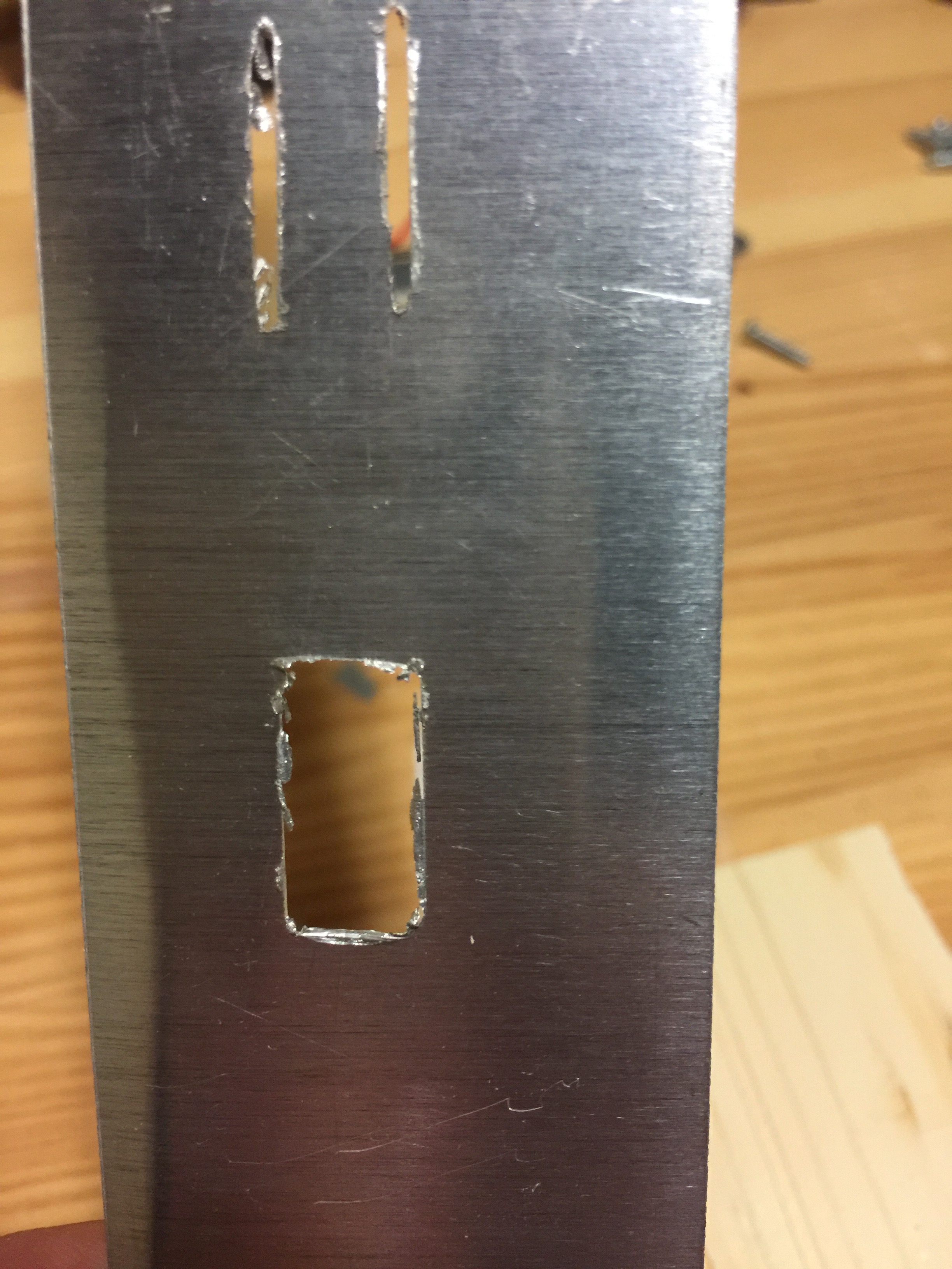
Next we have the potentiometer. The shaft, the volume knob, sticks out the front of the machine, so the body of the potentiometer also sits near to the front, but not perfectly flush with the front surface. It actually sits about a 1/4" back from the front surface. That's great, because out of the back 2/4" I could dremel out a small indentation to make room for the round top of the pot. And from the front, there is no difference. The metal plate still only needs to go up to the just overlap the edge of the main cutout.
These two images should show pretty clearly what I'm describing, and what I mean by the indentation to make room for the pot, that only needs to be in the back 2/3s of the thickness of the wood panel.


You know, in afterthought, I probably didn't need to do this next step. But at the time that I was putting it together, I was really concerned about the structural integrity of the soft wood. What was once a solid piece of wood many inches tall, was now broken up in to numerous thin bridges. From the top to a speaker hole is just 3/4". From the speaker hole through to the I/O cutout is even less maybe a half an inch max, including the thinned section for insetting the speaker, and it had already been damaged and partially glued back together.
I decided to reinforce the panel on the backside with metal strip plates. The downside is that they're kind of weighty. And, as I say, once everything is together there isn't actually much stress on this panel. So they probably weren't necessary, but, they're there.
Here's how the panel finally looks, when it's placed on the front of the chassis, with the speaker holes, and I/O board seated throught the I/O cutout.


Next, just like the Rear I/O Panel, we need to have a metal cover plate for the front I/O ports.
I used exactly the same sheet aluminum, scored and broke off a piece the right size for the front I/O cutout. So, the bottom plat of the chassis is 3/4" thick, and then the 1/2" thich I/O mount board is on top of that to hold the components. The metal plate will be screwed into the front edge of the mount board. The theory was that the mount board could be removed and with it would come the metal plate. It's not going to work out quite so nicely, because of that potentiometer issue. But the metal plate's bottom edge will still be right at the seam where the mount board and the bottom plate of the chassis meet.
On the left and right, the metal plate should be just wider than the I/O cutout, so that it overlaps the edges and completely covers the cutout. Same for the height. In this case, there is just enough room for the plate to cover the top of the cutout, and still be below the red chrome speaker grills. But just barely, the top of the metal plate will actually touch the bottom of the plastic chrome.

There isn't too much to say about how I measured out the places for the holes to be dremelled in the cover plate. I used a high quality metal ruler and just measured. I drew the guidelines on the back side of the plate with pencil.
Before actually starting to cut into the plate, I eyeballed as well as I could to confirm that my measurements at least looked approximately right. If you make several holes, and then you screw one of those holes up, you really screw yourself over. Any mistake in the metal plate more or less requires you to start again.


The holes for the power button and the volume knob, I made with simple drill bit. For the joystick controller ports, I made continuous guide lines that run along the tops and bottoms of all four ports. Then I interrupted those guides with the vertical splits.
Technically, a DB9 socket is trapezoidal, not rectangular. But none of this has the precision for it to really matter. My skill at dremelling, the dremel precision itself, and even the measuring process, nothing is precise enough to warrant trying to make the holes subtly trapezoidal. And even more specifically, the corners of a DB9 socket are not pointy but round. Doing this with the dremel is basically impossible.
Well, how do the pros do it then? Plenty of DB9 holes have been punched through sheet metal and they look pristine. I went looking online for a DB9 sheet metal punch, and I found a few. The least expensive one I found was $200 USD, just for the punch, that's not including the machine the punch is designed to be fit into. The most expensive was over $900 USD. So, my DB9 holes will be rectangles.

Once the essential retangular hole is cut through the sheet metal, a fine square metal file can be used to remove the burrs. The file can also be used to even out any rough edges, and straighten out the corners.
The most important thing is that a joystick cable can easily pass through the hole and connect to the DB9 port behind it. And that all 4 holes line up at the same time. I can do that test quite easily without needing to permenantly attach the panel. The volume knob and power switch can hole it in place and keep it oriented.


Once the front panel will be screwed permenantly onto the front of the chassis, the metal I/O cover will be attached to the front edge of the front I/O mount board, just like with the rear I/O mount board.
My friend Brad pointed out that it looks like a smiling robot. And it totally does! The speaker holes are like its big doe eyes, and the I/O opening is its mouth, complete with spaced out teeth made of metal, like it's wearing braces.


You can clearly see where the metal plate will have to be mounted. The I/O mount board is 1/2" thick. I want the screws to go smack in the middle of that. So we can measure the holes up a 1/4" from the bottom edge of the plate. And three screws seems sufficient.
The middle screw therefore should be centered. It will be between the two middle joystick controller port holes. And the other two to the left and right equidistant from the center. These holes, after their center points were marked and measured, I drilled through on the bench, and filed off the burrs.
Unlike for the rear I/O panel, which can easily be removed, for the front panel I put the plate in place, over the power switch and volume knob, then taped it on to hold it in place, and eye-balled the alignment with the joystick ports to make sure they looked centered. Then I drilled a couple of small pilot holes in the wood by passing through the existing holes in the metal for alignment. I screwed the plate on to see how it looked and how it fit. But ultimately had to remove it for being able to remove the front chassis panel. To prep that panel, then screw it on and eventually to paint it.
I didn't want to take the metal cover plate on and off any more than necessary, because I don't want to wear out or losen the screw holes.


Lastly, we have to wire up the speakers and the amplifier.
I picked up a short 3.5mm to stereo RCA audio cable at a local shop. I could build one of these but I just decided to buy one instead. It's 3 feet long, so I coiled it up neatly and held the coil with some zip ties.
After snipping the zip ties it holds together in a nice little ring that can easily be tucked away between the speakers. Additionally, we need the the speaker wire, a pair of wires with wide and narrow terminals for connecting to the speakers.


With the speakers mounted in the front panel, their terminals oriented towards the center, it's super easy to take the speaker wire from from the amplier and just pop them onto the speaker terminals.
After my botched job trying to solder the terminals on, I finally got an actual crimping tool. Above you can see the cables as they look when they've been properly crimped.
In addition to coiling up the RCA audio cable, I also put some zip ties on a coil of the cable leading to the AT power supply's switch. This neatly gets it tucked out of the way. And everything feels like it's got a place.


Last modified: Sep 20, 2022